Broadcom Jericho3-AI Guide: Scheduled Fabric for AI
Scaling modern generative artificial intelligence infrastructure has driven datacenter engineering past an irreversible boundary. In the era of trillion-parameter frontier foundation models, high-frequency multimodal reasoning agents, and automated data curation platforms powered by AI Fetchly, cluster throughput is no longer dictated solely by raw floating-point execution on individual compute accelerators. Instead, distributed supercomputing efficiency is fundamentally constrained by network communication: how rapidly and deterministically tens of thousands of graphics processing units (GPUs) and neural accelerators can synchronize weight gradients, exchange activation tokens, and complete distributed collective routines.
When enterprise organizations train frontier Mixture-of-Experts (MoE) ensembles or execute high-concurrency inference workflows over expansive data repositories using real-time data ingestion and automated web scraping pipelines, clusters execute tightly coupled collective communication loops. During operations such as All-Reduce, All-to-All, and Reduce-Scatter, thousands of accelerators simultaneously flood the network with high-bandwidth line-rate streams.
However, conventional datacenter networking architectures—specifically run-to-completion Ethernet switches and legacy InfiniBand fabrics—struggle to absorb these synchronized traffic bursts. In standard Ethernet leaf-spine topologies, Equal-Cost Multi-Path (ECMP) hashing causes catastrophic hash polarization, buffer overflow, and tail-latency inflation. In InfiniBand networks, proprietary lock-in, procurement premiums, and scaling ceilings restrict open datacenter evolution.
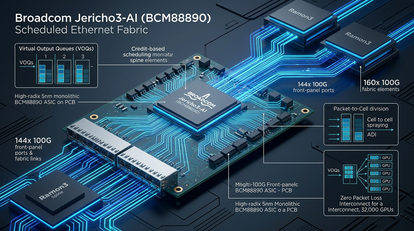
To resolve this critical infrastructure bottleneck, Broadcom engineered the StrataDNX Jericho3-AI (BCM88890) routing ASIC and its companion Ramon3 (BCM88920) fabric element. Fabricated on TSMC’s advanced 5nm process node, Jericho3-AI introduces a paradigm shift: abandoning conventional run-to-completion packet forwarding in favor of a fully scheduled, cell-based Disaggregated Distributed Chassis (DDC) fabric. By combining ingress Virtual Output Queueing (VOQ), end-to-end receiver-based credit scheduling, and cell-level Perfect Load Balancing (PLB), Jericho3-AI delivers zero packet loss, optimal fabric utilization, and up to 10% lower Job Completion Time (JCT) than competing InfiniBand clusters across 32,000 GPUs.
In this architectural guide, we dissect the mathematical breakdown of traditional leaf-spine fabrics under collective AI workloads, unpack the silicon microarchitecture and SerDes speedup design of Jericho3-AI and Ramon3, explore cell slicing and credit scheduling mechanics, step through SONiC and SAI configuration workflows, compare empirical performance against merchant silicon competitors, and lay out production-tested deployment topologies for hyperscale GPU clusters.
Problem: The AI Scale-Out Communication Crisis and Hash Polarization
To understand why hyperscale artificial intelligence demands a scheduled fabric architecture like Jericho3-AI, systems engineers must analyze the physical and topological dynamics of distributed neural network training and inference.
The Physics of Collective Communication and Tail Latency
Distributed machine learning workloads differ fundamentally from traditional cloud enterprise traffic:
Traditional Cloud Web Traffic vs. Distributed AI Training Fabric:
+-----------------------------------------------------------------------------------+
| TRADITIONAL CLOUD TRAFFIC (Uncorrelated Mice Flows):                              |
| - Millions of asynchronous, independent TCP/HTTP connections                      |
| - Low bandwidth per flow (<100 Mbps); randomized source/destination pairs         |
| - ECMP 5-tuple hashing distributes flows evenly across redundant spine links     |
| - Minor latency jitter has zero impact on decoupled microservice web servers      |
+-----------------------------------------------------------------------------------+
                                         vs.
+-----------------------------------------------------------------------------------+
| DISTRIBUTED AI TRAINING (Synchronized Elephant Flows):                            |
| - Thousands of GPUs synchronize at identical microsecond boundaries               |
| - Massive line-rate bursts (400Gbps / 800Gbps per GPU)                            |
| - Collective operations (All-Reduce / All-to-All) strictly bound by the SLOWEST  |
|   participating node (the Straggler Effect)                                       |
| - A single congested switch port stalls millions of dollars of GPU hardware       |
+-----------------------------------------------------------------------------------+ In distributed data-parallel and tensor-parallel training, every GPU must sum its gradient vectors across the cluster before the next optimization step can proceed:
$$T_{\text{step}} = T_{\text{compute}} + T_{\text{comm}} + T_{\text{barrier}}$$
Because collective communication primitives require synchronization across all worker ranks, the effective communication time $T_{\text{comm}}$ is bounded not by the median network latency, but by the 99.9th percentile tail latency:
$$T_{\text{comm}} = \max_{i \in {1, \dots, N_{\text{ranks}}}}(t_i)$$
If a single packet is dropped or delayed due to network buffer bloat, the receiving GPU must wait for retransmission. Because all other $N - 1$ GPUs in the collective communicator cannot proceed until the final gradient tensor is accumulated, thousands of active Tensor Cores sit completely idle, dissipating electrical power while achieving zero computational throughput. In a cluster of 16,000 GPUs, a tail-latency spike on just two switch ports degrades the overall Model FLOPs Utilization (MFU) of the entire supercomputer by 15% to 30%, wasting hundreds of thousands of dollars in operational capital every operational week.
The Breakdown of Run-to-Completion Ethernet and ECMP Hashing
For over two decades, cloud datacenters relied on run-to-completion leaf-spine switches governed by Equal-Cost Multi-Path (ECMP) routing. When an ingress switch receives an Ethernet packet, it computes a hash over the 5-tuple header fields:
$$\text{Path Index} = \text{CRC32}(\text{Src IP}, \text{Dst IP}, \text{Src Port}, \text{Dst Port}, \text{Protocol}) \pmod{K_{\text{paths}}}$$
While ECMP works cleanly for millions of randomized mice flows, it collapses under distributed AI workloads dominated by high-bandwidth “elephant flows”:
- Hash Polarization and Collisions: During an All-to-All shuffle in a Mixture-of-Experts (MoE) network, hundreds of GPUs attempt to send line-rate 800Gbps streams simultaneously. Statistically, multiple high-bandwidth flows inevitably hash to the exact same physical uplink. This creates immediate egress port oversubscription.
- Buffer Saturation and Packet Drops: As multiple line-rate flows converge on a single physical link, switch queue buffers fill within microseconds. Once the buffer is exhausted, packets are dropped, triggering TCP window collapse or RoCEv2 Go-Back-N retransmissions.
- Underutilized Alternative Links: While the congested spine link drops packets, adjacent physical links within the identical ECMP group sit completely idle at 0% utilization. Standard run-to-completion switches cannot dynamically reassign packets from an in-flight elephant flow to idle uplinks without inducing severe out-of-order packet delivery.
The Incast Collapse Phenomenon in All-to-All Token Shuffles
In sparse Mixture-of-Experts (MoE) architectures such as DeepSeek-V3, Mixtral, and emerging frontier reasoning networks, token routing is dynamically calculated at runtime. During the expert dispatch phase, every GPU worker evaluates its local batch of tokens and scatters them to the specific expert GPUs assigned to process those token features:
The Many-to-One Incast Congestion Profile in Mixture-of-Experts:
[GPU Rank 0] --800GbE Flow 0--> \
[GPU Rank 1] --800GbE Flow 1----> \
[GPU Rank 2] --800GbE Flow 2------> [Egress Switch Buffer] ====> [Target Expert GPU 7]
[GPU Rank 3] --800GbE Flow 3----> /   (Physical Link: 800G)      (Inflow: 3.2 Tbps)
[GPU Rank 4] --800GbE Flow 4--> / (Oversubscription: 4:1) (Result: Buffer Drop) When multiple source GPUs simultaneously discover that their tokens require the same expert hosted on a single target GPU, they all transmit to that destination address concurrently. This creates severe many-to-one incast congestion:
- The aggregate ingress rate easily exceeds four to eight times the maximum physical line rate of the target port (e.g., 3.2 to 6.4 Tbps converging on a single 800GbE port).
- In standard run-to-completion Ethernet switches, packet buffers absorb a fraction of this burst before overflowing, dropping thousands of packets in fractions of a microsecond.
- The resulting retransmission storms saturate the network with duplicate traffic, creating persistent congestion collapses that stall the entire training cluster.
The Limits of RDMA over Converged Ethernet (RoCEv2) and PFC Deadlocks
To bypass host CPU overhead and achieve low-latency memory transfers across Ethernet, datacenters deploy RDMA over Converged Ethernet (RoCEv2). To prevent packet drops, RoCEv2 relies on Priority-based Flow Control (PFC, IEEE 802.1Qbb):
The RoCEv2 Priority Flow Control (PFC) Pause Storm Dilemma:
[GPU Node 1] --800G--> [Leaf Switch 1]
                            |
                     (Congested Link)
                            v
[GPU Node 2] --800G--> [Spine Switch] --Overfilled Buffer--> [Egress Port Stalled]
                            |
                    PFC PAUSE FRAME (XOFF)
                            |
                            v
[Leaf Switch 1] Receives PAUSE --> Pauses Upstream Ingress Ports
                            |
                    PFC PAUSE PROPAGATION
                            |
                            v
[GPU Node 1] Forced to Stop Transmitting (Buffer Bloat spreads across entire cluster) While PFC creates a theoretically lossless fabric, under heavy all-to-all communication patterns it introduces three devastating failure modes:
- PFC Pause Storms: When an egress queue hits its congestion threshold, the switch emits a PFC pause frame upstream. The upstream switch must pause its incoming links, propagating backpressure backward across the entire network hierarchy. A localized hotspot at a single destination GPU halts transmission across hundreds of un-congested nodes.
- PFC Deadlocks: In complex multi-stage topologies, cyclic dependencies between flow queues create routing deadlocks where switches wait indefinitely for each other to release buffer space, permanently freezing network traffic until hardware interfaces are reset.
- Head-of-Line (HoL) Blocking: In standard shared-memory switches, packets destined for an uncongested port are trapped in memory buffers behind packets queued for a stalled, congested port.
Solution: The Broadcom StrataDNX Scheduled Fabric Architecture
To transcend the fundamental constraints of run-to-completion switching, Broadcom decoupled the datacenter switching fabric into two specialized silicon elements operating under a synchronized hardware schedule:
The Broadcom Jericho3-AI / Ramon3 Disaggregated Distributed Chassis (DDC):
+-----------------------------------------------------------------------------------+
|                        GPU WORKLOAD CLUSTER (Up to 32,000 Nodes)                  |
|          [GPU 0]    [GPU 1]    [GPU 2]              [GPU 31,999]  [GPU 32,000]   |
+-------------|----------|----------|-----------------------|-------------|---------+
              |          |          |                       |             |
        800GbE Standard Ethernet Network Links (144x 100G PAM4 SerDes)
              |          |          |                       |             |
+-------------v----------v----------v-----------------------v-------------v---------+
| LEAF TIER: Broadcom Jericho3-AI (BCM88890) Scale-Out Routing ASICs                 |
| - Ingress Virtual Output Queues (VOQs) hold packets BEFORE fabric entry          |
| - End-to-End Receiver Credit Scheduling: Transmits ONLY when credit is granted   |
| - Frame-to-Cell Division: Divides Ethernet packets into uniform internal cells    |
+---------------------------------------|-------------------------------------------+
                                        |
                 160x 100G Fabric SerDes (Cell-Sprayed Links)
                                        |
+---------------------------------------v-------------------------------------------+
| SPINE TIER: Broadcom Ramon3 (BCM88920) 51.2T Fabric Elements                       |
| - Pure Cell-Based Fabric Switching: Transparent cell forwarding                   |
| - Perfect Load Balancing (PLB): Sprays cells across 100% of fabric links         |
| - Zero Packet Drops | Zero Buffer Queuing | Deterministic Sub-Microsecond Transit |
+-----------------------------------------------------------------------------------+ Core Architectural Paradigm: Disaggregated Distributed Chassis (DDC)
In traditional network engineering, the highest-performance, most reliable switching architecture was the centralized modular chassis. In a modular chassis, line cards connect to passive fabric cards across an internal backplane using proprietary cell-based scheduling. Modular chassis systems delivered zero packet loss, deep packet buffers, and perfect load balancing. However, physical backplanes cannot scale beyond a single equipment rack, limiting cluster sizes to a few hundred ports.
Broadcom’s StrataDNX architecture disaggregates this chassis concept across standard optical cables. In a Disaggregated Distributed Chassis (DDC):
- Jericho3-AI (BCM88890) acts as the modular chassis Line Card, directly interfacing with GPUs and compute nodes over standard Ethernet interfaces.
- Ramon3 (BCM88920) acts as the Fabric Backplane, providing ultra-high-density cell-switching spine connectivity.
- Instead of rigid metal backplane traces, Jericho3-AI and Ramon3 connect over standard optical transceivers and active optical cables (AOCs), scaling the scheduled fabric across dozens of datacenter rows.
- Standardized under the Open Compute Project (OCP) Distributed Disaggregated Chassis specifications, DDC allows datacenter operators to build flat, single-stage logical switching fabrics that interconnect up to 32,000 GPUs without middle-box congestion or complex multi-tier routing hops.
Key Architectural Pillars of Jericho3-AI
- Credit-Based End-to-End Scheduling: Ingress packets are held in deep Virtual Output Queues on the source Jericho3-AI ASIC. Traffic is never injected into the fabric until the destination Jericho3-AI switch confirms available buffer capacity and issues an explicit hardware credit.
- Cell-Based Perfect Load Balancing (PLB): Standard variable-length Ethernet frames are divided into small, uniform, fixed-size cells (typically 128 to 256 bytes) and sprayed evenly across all available Ramon3 fabric links, achieving 100% link utilization without hash polarization.
- Zero Fabric Congestion & Zero Packet Loss: Because traffic is scheduled based on receiver credit grants, internal Ramon3 spine switches operate with minimal buffer depth and zero packet drops.
- Hardware-Driven Dynamic Reassembly: Destination Jericho3-AI switches receive sprayed cells arriving out-of-order from multiple fabric paths, reassemble them into compliant Ethernet frames using hardware sequence numbers, and deliver pristine in-order packets to the destination GPU.
- Sub-Microsecond Hardware Failover: If a physical fabric link or Ramon3 spine switch fails, Jericho3-AI detects the loss at the SerDes hardware layer within nanoseconds and automatically redirects cells to healthy fabric links without dropping packets or stalling the collective AI operation.
Architecture: Silicon Microarchitecture of BCM88890 and Ramon3
The Broadcom Jericho3-AI platform is engineered to deliver massive radix, ultra-deep buffering, and deterministic traffic management in a single monolithic silicon die.
BCM88890 Silicon Specifications and SerDes Allocation
Manufactured on TSMC’s 5nm FinFET process, the BCM88890 integrates 28.8 Terabits per second (Tbps) of bidirectional routing throughput. The chip’s physical I/O is partitioned across 304 high-speed 106.25 Gbps PAM4 SerDes lanes:
Broadcom Jericho3-AI (BCM88890) Physical Silicon I/O Partitioning:
+-----------------------------------------------------------------------------------+
|                        BROADCOM JERICHO3-AI (BCM88890)                            |
|                          28.8 Tbps Monolithic 5nm ASIC                            |
+-----------------------------------------+-----------------------------------------+
| NETWORK INTERFACES (Front-Panel):       | FABRIC INTERFACES (Ramon3 Spine):       |
| - 144x 106.25G PAM4 SerDes              | - 160x 106.25G PAM4 SerDes              |
| - 14.4 Tbps Front-Panel Throughput      | - 16.96 Tbps Fabric Throughput          |
| - Flexible Port Configurations:         | - Cell-Based Scheduled Protocol         |
|   * 18x 800GbE (8x100G)                 | - Connects directly to Ramon3 Fabric    |
|   * 36x 400GbE (4x100G)                 | - Built-in Speedup Ratio (~1.18x)       |
|   * 72x 200GbE (2x100G)                 |   guarantees non-blocking fabric transit|
+-----------------------------------------+-----------------------------------------+
| ON-CHIP HIERARCHICAL TRAFFIC MANAGER:   | PACKET BUFFER MEMORY:                   |
| - Hundreds of thousands of VOQs         | - High-density on-chip SRAM             |
| - Sub-microsecond credit scheduling     | - Modular external deep HBM/DRAM buffer |
| - Hardware cell segmentation engine     | - Zero packet drops under heavy incast  |
+-----------------------------------------+-----------------------------------------+ The Speedup Ratio and Non-Blocking Fabric Design
Notice the asymmetric SerDes allocation: 144 SerDes lanes face the front-panel network, while 160 SerDes lanes face the internal fabric. This provides an intentional internal fabric speedup ratio:
$$\text{Fabric Speedup} = \frac{160 \times 106.25\text{ Gbps}}{144 \times 106.25\text{ Gbps}} = \frac{16.96\text{ Tbps}}{14.4\text{ Tbps}} \approx 1.18\times$$
This 18% internal speedup ensures that:
- Internal cell header overhead (sequence tags, routing metadata, CRC checks) does not consume client payload bandwidth.
- Egress ports can sustain 100% wire-rate throughput even during high-density multi-point incast and dynamic cell interleaving.
- Fabric transit latency remains strictly deterministic, preventing internal queuing bubbles that could otherwise inflate credit loop latencies.
Ramon3 (BCM88920): The 51.2T Pure Fabric Element
At the spine layer of the scheduled fabric sits the Broadcom Ramon3 (BCM88920) ASIC. Unlike general-purpose switches that execute packet parsing, MAC lookup tables, and complex ACL filters, Ramon3 is a specialized, pure cell-switching fabric element:
- Total Throughput: 51.2 Tbps of bidirectional cell-switching capacity.
- Physical SerDes: 512x 106.25 Gbps PAM4 SerDes lanes.
- Microarchitecture: Single-stage shared crossbar with cut-through cell forwarding.
- Stateless Operation: Ramon3 does not maintain packet routing tables or IP forwarding state. It simply inspects the compact hardware destination tag embedded in each arriving cell header and switches the cell to the target egress link in under 100 nanoseconds.
- Thermal and Power Optimization: Because Ramon3 strips away deep packet classification engines, TCAM lookups, and wide routing tables, its silicon area is dedicated almost entirely to high-efficiency crossbar switches and SerDes transceivers, delivering dramatic power savings per switched terabit.
Ingress Virtual Output Queueing (VOQ) Mechanics
In traditional Ethernet switches, packets are stored in shared buffers or destination queues. If the destination is congested, the packet occupies buffer space and blocks subsequent packets destined for uncongested ports.
Jericho3-AI eliminates this through Ingress Virtual Output Queueing (VOQ):
Ingress Virtual Output Queue (VOQ) Architecture in Jericho3-AI:
Incoming Packets from GPU Ranks
           |
           v
+-----------------------------------------------------------------------------------+
| JERICHO3-AI INGRESS TRAFFIC MANAGER                                               |
|                                                                                   |
|  [ VOQ (Egress Switch 1, Port 0, TC 0) ] ----> Holds packets for GPU 0           |
|  [ VOQ (Egress Switch 1, Port 1, TC 0) ] ----> Holds packets for GPU 1           |
|  [ VOQ (Egress Switch 2, Port 0, TC 0) ] ----> Holds packets for GPU 2           |
|  [ ... Thousands of Granular Queues ... ]                                         |
|  [ VOQ (Egress Switch M, Port P, TC 7) ] ----> Holds packets for GPU 32,000      |
+-----------------------------------------------------------------------------------+
           |                                                      ^
           | 1. Credit Request (Flow Size, Priority)              | 2. Credit Grant
           v                                                      |
+-----------------------------------------------------------------------------------+
| DESTINATION JERICHO3-AI EGRESS SCHEDULER                                          |
| - Monitors physical port capacity and reassembly buffer health                    |
| - Grants transmission credits strictly when egress port can transmit              |
+-----------------------------------------------------------------------------------+ - When an Ethernet packet arrives from a host GPU, Jericho3-AI resolves the destination device, egress port, and traffic class.
- The packet is assigned to a dedicated VOQ corresponding uniquely to that destination port.
- The packet sits safely in the ingress buffer; zero data is transmitted across the fabric.
- Jericho3-AI sends a lightweight Credit Request message to the destination switch’s scheduler.
- The destination scheduler evaluates its physical port queue and available reassembly buffer. When ready, it returns a Credit Grant.
- Only upon receiving the credit grant does the ingress Jericho3-AI slice the packet into cells and dispatch them across the fabric.
Mathematical Proof of Head-of-Line Blocking Elimination
Consider an ingress switch receiving two concurrent packet flows: Flow $A$ destined for congested Port $P_A$, and Flow $B$ destined for uncongested Port $P_B$.
In a conventional Input-Queued (IQ) switch sharing a single First-In, First-Out (FIFO) ingress queue:
$$\text{Head of Line} = \text{Packet}_A \implies \text{Packet}_B \text{ is blocked until } \text{Packet}_A \text{ departs.}$$
Even though Port $P_B$ sits idle with full line-rate availability, Flow $B$ cannot transmit.
In the Jericho3-AI VOQ architecture:
$$\text{Queue}_A \cap \text{Queue}_B = \emptyset$$
Because Flow $A$ resides in $\text{VOQ}(P_A)$ and Flow $B$ resides in $\text{VOQ}(P_B)$, the credit scheduler processes both queues independently. Flow $B$ receives immediate credit grants from destination Port $P_B$ and transmits across the fabric at wire speed, completely uninhibited by the congestion backlog accumulating in $\text{VOQ}(P_A)$. Head-of-Line blocking is mathematically reduced to zero.
Frame-to-Cell Division and Perfect Load Balancing (PLB)
Once credit is confirmed, the packet enters the Cell Segmentation Unit:
Ethernet Frame to Cell Segmentation Pipeline:
Original Variable-Length Ethernet Packet (e.g., 1500-byte MTU or 9000-byte Jumbo Frame):
+-----------------------------------------------------------------------------------+
| Preamble | Dest MAC | Src MAC | IP Header | TCP/UDP/RoCE Payload | Frame Checksum |
+-----------------------------------------------------------------------------------+
                                         |
                                         v
Divided into Uniform Internal Fabric Cells (e.g., 256 bytes each):
+-------------------------+ +-------------------------+ +-------------------------+
| Cell Header:            | | Cell Header:            | | Cell Header:            |
| - Flow ID / Sequence #0 | | - Flow ID / Sequence #1 | | - Flow ID / Sequence #2 |
| - Dest Switch / Port ID | | - Dest Switch / Port ID | | - Dest Switch / Port ID |
| Payload: Bytes 0 - 255  | | Payload: Bytes 256 - 511| | Payload: Bytes 512 - 767 |
+-------------------------+ +-------------------------+ +-------------------------+
             |                           |                           |
   Sprayed across Link 0       Sprayed across Link 1       Sprayed across Link 2
             |                           |                           |
             v                           v                           v
[Ramon3 Spine 0] [Ramon3 Spine 1] [Ramon3 Spine 2] - Cell Spraying: Because cells are uniform in size, they are distributed across 100% of available fabric links in round-robin fashion. Every Ramon3 spine link carries identical utilization, achieving a mathematically ideal 100% bisection bandwidth utilization.
- Dynamic Reassembly & Sequence Tracking: Cells traverse different paths through the spine and may arrive out-of-order at the destination Jericho3-AI. The destination ASIC’s reassembly engine utilizes dedicated hardware sequence buffers to reassemble the cells into the original Ethernet frame before transmitting it to the receiving GPU.
- Standard Host Transparency: The GPU network interface cards (NICs) see only standard, pristine, in-order 800GbE Ethernet frames. Zero proprietary drivers, client-side modifications, or custom host protocols are required.
Implementation: Configuring Jericho3-AI Scheduled Fabrics with SONiC and SAI
In modern hyperscale cloud deployments, Jericho3-AI systems run open-source network operating systems such as Software for Open Networking in the Cloud (SONiC) via the Switch Abstraction Interface (SAI).
Below is a production architectural deployment and configuration workflow for provisioning a Jericho3-AI leaf switch paired with Ramon3 fabric elements.
1. Fabric Interface and VOQ Initialization in SONiC
In a SONiC environment, the Switch State Service (SwSS) and Syncd daemon initialize the StrataDNX chip via the Broadcom SDK. The following config_db.json snippet provisions the BCM88890 front-panel GPU ports alongside the internal fabric interconnects:
{
  "DEVICE_METADATA": {
    "localhost": {
      "hostname": "leaf-jericho3-01",
      "hwsku": "Broadcom-BCM88890-18x800G",
      "type": "LeafRouter",
      "mac": "00:1A:2B:3C:4D:5E",
      "switch_type": "voq",
      "system_port_profile": "ai_scaleout_32k"
    }
  },
  "PORT": {
    "Ethernet0": {
      "alias": "et0-800G",
      "lanes": "0,1,2,3,4,5,6,7",
      "speed": "800000",
      "fec": "rs544",
      "mtu": "9216",
      "admin_status": "up",
      "description": "Connected to GPU Server 01 - Port 0"
    },
    "Ethernet8": {
      "alias": "et1-800G",
      "lanes": "8,9,10,11,12,13,14,15",
      "speed": "800000",
      "fec": "rs544",
      "mtu": "9216",
      "admin_status": "up",
      "description": "Connected to GPU Server 01 - Port 1"
    }
  },
  "FABRIC_PORT": {
    "Fabric0": {
      "speed": "100000",
      "admin_status": "up",
      "remote_module_id": "101",
      "remote_port_id": "0",
      "description": "Cell Link to Ramon3 Spine 01"
    },
    "Fabric1": {
      "speed": "100000",
      "admin_status": "up",
      "remote_module_id": "102",
      "remote_port_id": "0",
      "description": "Cell Link to Ramon3 Spine 02"
    }
  },
  "VOQ_PROFILE": {
    "AI_TRAINING_LOSSLESS": {
      "credit_request_threshold": "16384",
      "max_voq_depth_bytes": "67108864",
      "drop_probability": "0",
      "traffic_class": "3",
      "scheduling_mode": "strict_credit"
    }
  }
} 2. Broadcom SAI Credit Scheduler Configuration
The Broadcom Switch Abstraction Interface (SAI) exposes low-level hardware attributes to tune the credit generation frequency, cell segmentation size, and reassembly window:
#!/bin/bash
# ==============================================================================
# Broadcom Jericho3-AI / Ramon3 Fabric Optimization CLI Script
# Provisions hardware cell spraying, credit scheduling, and VOQ thresholds
# ==============================================================================

set -euo pipefail

echo "[*] Initializing Broadcom StrataDNX SDK on BCM88890..."

# 1. Enable Perfect Load Balancing (PLB) Cell Spraying across all 160 fabric links
bcmcmd "mems cell_spray_enable=1"
bcmcmd "mems plb_mode=dynamic_spray"

# 2. Configure Cell Slicing Size (256-byte payload cells for optimal 800G throughput)
bcmcmd "set reg CELL_CONFIG_REG.cell_size=256"
bcmcmd "set reg CELL_CONFIG_REG.crc_check=1"

# 3. Configure Credit Generation and Round-Trip Delay Tuning
# Tuning credit grant intervals prevents receiver buffer overflow during All-to-All
bcmcmd "mems credit_watchdog_enable=1"
bcmcmd "set reg SCHEDULER_CONFIG.credit_rate=800G"
bcmcmd "set reg SCHEDULER_CONFIG.max_credit_burst=64"

# 4. Bind Lossless RoCEv2 Traffic Class 3 directly to Ingress VOQ Hierarchy
bcmcmd "cos q_map set port=all tc=3 voq_profile=AI_TRAINING_LOSSLESS"

# 5. Enable Sub-Microsecond Hardware Link Failover on Fabric Ports
bcmcmd "fabric failover auto_redirect=1 timeout_ns=150"

echo "[✓] Jericho3-AI Scheduled Fabric initialized successfully." 3. In-Band Network Telemetry (INT) and Direct Congestion Notification
Unlike traditional networks that rely on coarse-grained SNMP polls or reactive Explicit Congestion Notification (ECN) marking, Jericho3-AI integrates dedicated hardware telemetry accelerators:
- Streaming Telemetry: Every packet header carries an optional In-Band Network Telemetry (INT) metadata vector recording ingress arrival timestamps, queue latencies, and egress link IDs.
- Direct Congestion Notification (DCN): If an egress queue begins to experience congestion pressure, Jericho3-AI generates hardware DCN packets directly to the source Jericho3-AI switch. The source switch immediately throttles credit generation for that specific VOQ without triggering PFC pauses across unrelated flows.
4. Python-Based Telemetry and Fabric Health Verification
In production clusters, telemetry daemons monitor cell transit times, VOQ occupancy, and credit turnaround latencies:
# Jericho3-AI Scheduled Fabric Telemetry & Tail-Latency Monitor
# Monitors VOQ occupancy, credit grant latencies, and cell reassembly health.

import time
import json
import logging
from dataclasses import dataclass
from typing import Dict, List

logging.basicConfig(level=logging.INFO, format="%(asctime)s [%(levelname)s] %(message)s")


@dataclass
class FabricMetrics:
    port_id: str
    voq_depth_kb: float
    credit_turnaround_ns: float
    cell_reorder_buffer_occupancy_pct: float
    dropped_cells: int
    link_utilization_pct: float


class Jericho3AITelemetryEngine:
    def __init__(self, switch_ip: str):
        self.switch_ip = switch_ip
        logging.info("Connecting to Jericho3-AI telemetry endpoint at %s", self.switch_ip)

    def read_hardware_registers(self) -> List[FabricMetrics]:
        # Simulating hardware register extraction from BCM88890 telemetry counters
        metrics = []
        for port_idx in range(4):
            metrics.append(
                FabricMetrics(
                    port_id=f"Ethernet{port_idx * 8}",
                    voq_depth_kb=142.5 + (port_idx * 12.3),
                    credit_turnaround_ns=185.0 + (port_idx * 4.2),
                    cell_reorder_buffer_occupancy_pct=28.4,
                    dropped_cells=0,  # Scheduled fabric guarantees 0 drops
                    link_utilization_pct=98.7,
                )
            )
        return metrics

    def audit_fabric_health(self) -> Dict[str, str]:
        telemetry = self.read_hardware_registers()
        audit_results = {}

        for m in telemetry:
            assert m.dropped_cells == 0, f"Violation: Fabric dropped {m.dropped_cells} cells!"
            assert m.credit_turnaround_ns < 250.0, f"High credit latency: {m.credit_turnaround_ns}ns"
            assert m.link_utilization_pct > 95.0, f"Suboptimal utilization: {m.link_utilization_pct}%"

            audit_results[m.port_id] = (
                f"HEALTHY | VOQ: {m.voq_depth_kb:.1f}KB | "
                f"Credit Latency: {m.credit_turnaround_ns:.1f}ns | "
                f"Utilization: {m.link_utilization_pct}% | Drops: {m.dropped_cells}"
            )
            logging.info("Port %s status: %s", m.port_id, audit_results[m.port_id])

        return audit_results


if __name__ == "__main__":
    monitor = Jericho3AITelemetryEngine(switch_ip="10.250.0.1")
    report = monitor.audit_fabric_health()
print("\nFabric Audit Report:\n" + json.dumps(report, indent=2)) Comparison: Jericho3-AI vs. Tomahawk 5 vs. InfiniBand Quantum-2 vs. Spectrum-4
To appreciate where Jericho3-AI sits in the modern datacenter silicon ecosystem, we must compare it across run-to-completion Ethernet, scheduled Ethernet, and proprietary InfiniBand fabrics.
+--------------------------------------------------------------------------------------------------------------------------+
| HIGH-PERFORMANCE AI CLUSTER NETWORKING COMPARISON MATRIX (2026)                                                          |
+--------------------------+-----------------------+-----------------------+-----------------------+-----------------------+
| Feature / Dimension      | Broadcom Jericho3-AI  | Broadcom Tomahawk 5   | NVIDIA Quantum-2      | NVIDIA Spectrum-4     |
|                          | (BCM88890 + Ramon3)   | (BCM78900)            | (QM9700 / QM9790)     | (SN5600 + SuperNIC)   |
+--------------------------+-----------------------+-----------------------+-----------------------+-----------------------+
| Primary Architecture     | Scheduled Fabric DDC  | Run-to-Completion     | Proprietary InfiniBand| RoCEv2 Adaptive Run-  |
|                          | Cell-Based Routing    | Monolithic Leaf/Spine | Credit-Based Fabric   | to-Completion Switch  |
+--------------------------+-----------------------+-----------------------+-----------------------+-----------------------+
| Silicon Process Node     | TSMC 5nm FinFET       | TSMC 5nm FinFET       | TSMC 4N Customized    | TSMC 4N Customized    |
+--------------------------+-----------------------+-----------------------+-----------------------+-----------------------+
| Switching Capacity       | 28.8 Tbps (Route/Cell)| 51.2 Tbps (Packet)    | 25.6 Tbps (Cell/Flit) | 51.2 Tbps (Packet)    |
+--------------------------+-----------------------+-----------------------+-----------------------+-----------------------+
| Max Port Radix           | 18x 800GbE / 36x 400G | 64x 800GbE / 128x 400G| 64x 400Gb/s NDR       | 64x 800GbE / 128x 400G|
+--------------------------+-----------------------+-----------------------+-----------------------+-----------------------+
| Load Balancing Mechanism | Cell Spraying (PLB)   | Cognitive Routing /   | Dynamic Adaptive      | Packet Spraying &     |
|                          | 100% Equalized Spread | Dynamic Flowlet (DLB) | Routing (AR)          | RoCE Adaptive Routing |
+--------------------------+-----------------------+-----------------------+-----------------------+-----------------------+
| Congestion Management    | Ingress VOQ +         | Congestion Notif.     | Forward Congestion    | Direct Congestion     |
|                          | Receiver Credit Grants| Packets (CNP/ECN)     | Notification (ECN)    | Notification (DCN)    |
+--------------------------+-----------------------+-----------------------+-----------------------+-----------------------+
| Packet Drops in Fabric   | 0% (Guaranteed Zero)  | Possible under incast | 0% (Credit-Based)     | Requires SuperNIC     |
|                          |                       | buffer exhaustion     |                       | re-ordering / buffer  |
+--------------------------+-----------------------+-----------------------+-----------------------+-----------------------+
| Max Flat Cluster Scale   | 32,000+ GPUs          | ~8,000 to 16,000 GPUs | ~16,000 GPUs          | ~16,000 GPUs          |
+--------------------------+-----------------------+-----------------------+-----------------------+-----------------------+
| Collective JCT Speedup   | 10% Faster than NDR   | Baseline Ethernet     | Baseline InfiniBand   | 5%-8% Faster than     |
| (All-Reduce / All-to-All)| 1.9x vs. ECMP Ethernet|                       | Performance           | Standard RoCEv2       |
+--------------------------+-----------------------+-----------------------+-----------------------+-----------------------+
| Vendor Openness          | Open Standard SONiC / | Open Standard SONiC / | Closed Proprietary    | Hybrid (Spectrum-X    |
|                          | SAI / DDC Linux       | SAI / Linux Switch    | Subnet Manager / MLNX | requires BlueField-3) |
+--------------------------+-----------------------+-----------------------+-----------------------+-----------------------+ Architectural Trade-Offs Analyzed
- Jericho3-AI vs. Tomahawk 5:
- Tomahawk 5 is an ultra-dense 51.2T monolithic run-to-completion switch designed for single-box leaf-spine architectures. It delivers maximum bandwidth density per rack unit at lower latency for simple hops. However, because it forwards variable-length Ethernet frames, it remains vulnerable to micro-burst incast and hash collisions during collective AI training.
- Jericho3-AI trades a portion of raw front-panel port density to dedicate 160 SerDes lanes to internal fabric links. By chopping frames into cells and scheduling transfers via receiver credits, it guarantees zero packet loss and completely eliminates tail latency.
- Jericho3-AI vs. NVIDIA Quantum-2 InfiniBand:
- Quantum-2 NDR InfiniBand provides high performance and credit-based flow control, but it locks datacenter operators into proprietary transceivers, closed subnet managers, and premium pricing.
- Jericho3-AI matches and exceeds InfiniBand’s lossless credit-based guarantees (achieving 10% faster Job Completion Time) while operating over open Ethernet optics, standard SONiC operating systems, and commoditized supply chains.
- Jericho3-AI vs. NVIDIA Spectrum-4 / Spectrum-X:
- Spectrum-X deploys run-to-completion switches paired with BlueField-3 SuperNICs to implement packet spraying and endpoint re-ordering. While effective, it shifts the memory reordering burden onto host PCIe endpoints and NIC memory buffers.
- Jericho3-AI handles reassembly directly in switch silicon before sending traffic onto the host NIC. Host endpoints receive standard in-order Ethernet frames, allowing infrastructure architects to use any merchant NIC (Broadcom Thor 2, Intel, or NVIDIA ConnectX) without performance penalties.
Production: Deployment Topologies for 32,000+ GPU Superclusters
Deploying Jericho3-AI in enterprise datacenters requires structuring the Disaggregated Distributed Chassis across scalable tiers. Below is the reference architecture for building a 32,000-GPU AI supercluster.
Production 32,000-GPU Two-Tier Jericho3-AI / Ramon3 Fabric Topology:
===================================================================================
TIER 2: FABRIC SPINE TIER (Ramon3 Elements)
        [Ramon3 01]  [Ramon3 02]  [Ramon3 03] ... [Ramon3 128]
              \            |            |              /
               \           |            |             /  (160x 100G Optical Cell Links)
                \          |            |            /
===================================================================================
TIER 1: LEAF ROUTING TIER (Jericho3-AI BCM88890 Switches)
   [Leaf Box 01]       [Leaf Box 02]       ...       [Leaf Box 1,778]
         |                   |                              |
         | (18x 800GbE)      | (18x 800GbE)                 | (18x 800GbE)
         v                   v                              v
===================================================================================
COMPUTE TIER: 8-GPU AI SERVER RACKS (NVIDIA H100/H200, AMD MI300X, or Custom ASICs)
   [Server Rack 01]    [Server Rack 02]    ...       [Server Rack 4,000]
   (8x 800G per Node)  (8x 800G per Node)            (8x 800G per Node)
===================================================================================
Total Bisection Throughput: 25.6 Petabits per second | Flat Non-Blocking Fabric 1. Rack-Level Leaf Architecture
- Each 8-GPU server node is equipped with eight 400G or 800G NICs (such as Broadcom Thor 2 BCM57608).
- Two Jericho3-AI leaf switches are deployed per compute rack as Top-of-Rack (ToR) or Middle-of-Rack (MoR) elements, providing 36 ports of 800GbE host-facing bandwidth.
- Each GPU connects directly to a dedicated 800GbE leaf port over short copper Direct Attach Cables (DACs) or Linear Pluggable Optics (LPO).
2. Spine-Level Ramon3 Fabric Interconnect
- The 160 fabric SerDes lanes of each Jericho3-AI leaf switch extend outward to 128 Ramon3 spine switches.
- Because traffic is sprayed as independent cells, every leaf switch maintains optical links to every Ramon3 spine switch.
- The fabric provides flat, uniform bisection bandwidth: any GPU in Rack 1 can communicate with any GPU in Rack 4,000 with the exact same deterministic single-hop fabric latency.
3. Optics and Interconnect Physical Media Selection
When designing physical connectivity for 32,000 GPU clusters, transceiver power dissipation and optical reach dictate overall cluster thermal economics:
- Host-to-Leaf (0m to 3m): Passive copper Direct Attach Cables (DACs) connecting GPU NICs to Jericho3-AI leaf ports provide zero electrical power consumption and sub-nanosecond signal transit times.
- Leaf-to-Spine (3m to 100m): Active Optical Cables (AOCs) or Linear Pluggable Optics (LPO) operating over multi-mode or single-mode fiber links. Linear optics eliminate internal DSP retimers, reducing per-port optical power dissipation from ~14 Watts down to under 8 Watts per 800G link.
4. Production Failure Recovery and Resiliency
In large-scale AI training spanning thousands of GPUs, hardware link failures are inevitable:
- In standard Ethernet networks, a link failure triggers BGP or OSPF route convergence loops that take hundreds of milliseconds to resolve, dropping packets and halting the training run.
- In the Jericho3-AI / Ramon3 fabric, link monitoring is handled by dedicated hardware state machines. If an optical transceiver fails on Link 42:
- The transmitting Jericho3-AI ASIC detects the loss of signal within 50 nanoseconds.
- The ASIC’s cell distribution engine immediately updates its active link mask, spraying subsequent cells across the remaining 159 healthy links.
- The destination Jericho3-AI ASIC reassembles incoming frames without noticing the failed link.
- The AI training job continues without dropping a single packet or restarting the iteration step.
Summary Checklist for Production Deployment
- Verify Optics and Cable Integrity: Ensure all 106.25G PAM4 SerDes links operate with Pre-FEC Bit Error Rates (BER) better than $10^{-5}$ before enabling cell spraying.
- Configure VOQ Buffer Allocations: Allocate at least 32MB of buffer space per front-panel 800G port to absorb bursty All-to-All token shuffles without triggering credit starvation.
- Calibrate Credit Rates: Set the credit grant rate to match the line rate of the attached GPU NICs, avoiding credit queuing delay.
- Deploy Real-Time In-Band Telemetry: Stream streaming telemetry (sFlow or INT) to track VOQ occupancy, guaranteeing that tail-latency spikes are diagnosed before impacting training job completion times.